Abaqus Meshing Tutorials - Meshing 3D Solid Fork end Solid Part in Abaqus

 Abaqus Meshing Tutorials - Meshing 3D Solid Fork end Solid Part in Abaqus

STEP 1
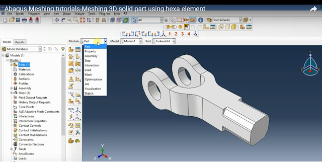
First step is to import 3D model from local drive to the abaqus 6.14.In this case i have model the part in Solidworks and saved in  .step extension in your local drive.To import the file to the abaqus,right click on the PART tab in the model tree in that select IMPORT option.Select the file from the local drive and import it.


STEP 2:
With the help of mesh module in Abaqus/CAE you can generate mesh in parts and assemblies.You can assign the mesh using different mesh characteristics such as element shape,element type and mesh density.you can also refine the mesh by seeding the mesh density in a particular regions.

You can also control the mesh by assigning different element shape such as Hex,Hex-dominated,Tet,Wedge in the case 3D solid part and Quad,Quad dominated and Tri in the case of shell part.

After importing the file GO TO Meshing Module by selecting MESH option in module tab.Select mesh control tab.

 STEP 3:
In this case you can choose different element shape.If i select TET type Free meshing technique the part will be meshed automatically.the TET type meshing is as shown in the image below.  


 STEP 4:
If i select HEX type of mesh,the part will not mesh automatically for that we have to partition the part properly if we want structured mesh or sweep type of meshing technique.

 
Step 5 :
For partitioning the 3D solid part,we have to use different methods of partition

 
Step 6:
In this case first i have selected CELL type and i have choosen DEFINE CUTTING METHOD technique for partioning.In this case first select POINT and then select normal straight line.

Step 7:
Next select EXTEND FACE option in the partition method and then select FACE and try to apply extend face option as maximum you can.

Step 8:
Try to use both the combination of meshing technique till the part get fully partioned.Fully partitioned and meshed part using both CUTTING METHOD technique and EXTEND face technique is as shown.


Abaqus Tutorials for beginners - Composite layup Static analysis (3D shell)


Abaqus Tutorials for beginners - Composite layup Static analysis (3D shell) 


In this tutorial, you will study how to create composite layup in Abaqus software and also we will study how to to define the material properties and the stacking sequence of the laminated composite structures. 


In this tutorial we will perform Linear static analysis in a laminated composite plate and visualize the results of the simulation with Abaqus/Viewer.In this case i have considered Rectangular plate subjected to edge load.

STEP 1.
The material properties used for this laminated composite plate is shown below

STEP 2 
For performing static analysis i have considered a rectangular plate of size 130*60mm. For creating the part in abaqus select 3D deformable with PLANAR SHELL type as modeling shape.

Select approximate size of the modeling space as 200 if your model dimension within this range.
If your part dimension more than 500 or 700mm,then put 1000 as a approximation size of your modeling space.


STEP 3 
After creating a part we have to apply the material properties for this select CREATE MATERIAL option.Put the name of material you are applying,then go to MECHANICAL-ELASTICITY-ENGINEERING CONSTANT.

For this case i have considered CARBON EPOXY MATERIAL which is already mentioned in the properties table shown above and put all the property values in box as shown below


STEP 4
After creating material library we have to assign those materials to a part.for that we have to choose CREATE COMPOSITE TAB  as mentioned below.


STEP 5
Then choose REGION and assign required thickness, in this case i have taken 0.3mm as thickness of each ply and given ply rotation as [0/45/-45] with symmetric ply orientation then OK.


STEP 6
After Assigning material properties ,select assembly module in that select CREATE INSTANCE-CHOOSE DEPENDENT PART-OK.


STEP 7
to apply analysis type go to step module-CREATE STEP OPTION-SELECT PROCEDURE TYPE AS GENERAL-STATIC GENERAL-OK.We are performing linear static analysis here for that we have to choose default option.


STEP 8
meshing is the most important step in any analysis for getting accurate solution.For this select OBJECT-PART-SELECT SEED PART-PUT 1 AS GLOBAL SEED SIZE-OK.go to ASSIGN MESH CONTROL and select HEX structured element type and THEN MESH THE PART. 


STEP 9
Next step is to apply loads and boundary conditions,  for this go to LOAD MODULE-CREATE BOUNDARY CONDITION-CHOOSE STEP AS INITIAL-SELECT CATEGORY AS MECHANICAL-SYMMETRY/ASSYMETRY/ENCASTRE-CONTINUE-select left region and select-ENCASTRE option so as to fix all degrees of freedom.

for apply edge load to the right side apply the boundary condition shown below


 STEP 10
give the edge load value as 100 N and press OK.

STEP 11
To see the stacking sequence of the composite layup go to Query. In the Query dialog box, select Visualization Module Queries in that select Ply stack plot then select the cover to display the composite lay up.


STEP 12
To submit the job go to JOB-CREATE JOB-CONTINUE-OK.then in the tree file,right click on the job-1 and submit the job.After completing job submission right click  on the job-1 and select RESULT option.


STEP 13
The results are as shown below


How to Mesh 3D Solid Part With Hole in Abaqus

How to Mesh the Plate with hole (3D Solid Part) in Abaqus 6.14

Meshing Module
With the help of mesh module in Abaqus/CAE you can generate mesh in parts and assemblies.You can assign the mesh using different mesh characteristics such as element shape,element type and mesh density.you can also refine the mesh by seeding the mesh density in a particular regions.

For solid part we have to select SOLID HOMOGENEOUS SECTION.We have to partition the solid part for structural meshing.


You can also control the mesh by assigning different element shape such as Hex,Hex-dominated,Tet,Wedge in the case 3D solid part and Quad,Quad dominated and Tri in the case of shell part.